Setout using Emlid Reach RS2 GNSS receivers
Before earthworks can be carried out on a site, the exact positions of key points of the design must be staked out. This helps the equipment operators visualise the job to be done. This is not just the latitude and longitude of key points – but also the elevation. This is known as set out, setting out or stake out.
In this post we cover Setout using Emlid Reach RS2 GNSS receivers. This process requires several steps to ensure the design is correctly translated onto the physical landscape.
Here’s an overview of the process
– Assess the scale of the project. Distance, vegetation and terrain may impact the ability of the rover to continuously receive the corrections data transmission from the base
– Establish a Base at a known location that can provide RTK correction data.
– Set up a Rover and connect to the Base.
– Stake out points on site with directions for machinery operators (cut and fill).
The Base Station
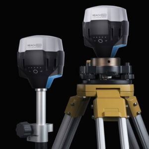
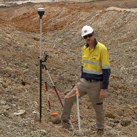
For improved accuracy on site, we set up a GNSS receiver as a Base at a known location. This is also known as our control point.
A second GNSS receiver acts as our dynamic unit – it moves around the site. This unit is usually referred to as the Rover.
This Base & Rover setup takes advantage of a technique known as Real Time Kinematic or RTK.
GNSS receivers collect position data from a number of satellites orbiting the earth. Changes in conditions can affect the transmission between the satellites and receiver unit, introducing an element of error. As the Base is stationary, these variations can shared to the Rover unit to calculate more precise positioning.
With Emlid Reach RS2 receivers, these corrections are shared from the Base to the Rover using LoRa (Long Range) radio.
Can’t locate a control point?
In some locations, you may not be aware of any existing control points. If you are working in Australia and need to look for some, try out the very handy app called Benchmrk. This App gives information on nearby controls and connects with online resources for related documentation.
In the video below, Alistair was working in a remote location with no known control points close at hand. This required the establishment of a control using a technique called Precise Point Positioning.
Make your own control point
Setting up the base station over a set point and allowing the receiver to collect position data for a minimum of 1 hour will generate a RINEX file. This file can then be uploaded to a service such as AUSPOS.
Depending on the requirements of your project, we recommend a minimum of 2 and up to 24 hours static observations. You can then be confident of coordinating your mark with the required accuracy.
We like to wait at least 2 days from the date of capturing the RINEX log before uploading to AUSPOS. This seems to provide the best balance between accuracy and expediency.
Before submitting your RINEX files – here is a free AUSPOS Checklist you can follow to ensure your job is processed with no hiccups.
If a site requires a longer term control point, try and pick a location that won’t be damaged. Heavy machinery and nature aren’t kind to exposed control points!
Set up the Rover
The second Emlid Reach RS2 acts as the Rover unit. It receives data from both the GNSS network and RTK corrections via LoRA from the Base unit.
Hardware
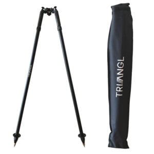
Adding a Bipod to the survey pole helps to stabilise the setup and frees up your hands when working in the field.
Other useful options include a device holder – something to hold your tablet or phone. We really like the Ram X-Grip kits as they are strong and dependable.
Software
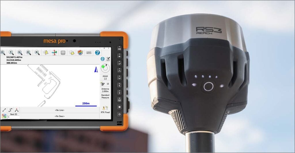
Reachview 3 is the free App from Emlid. It is available for Android or iOS.
Enter the height of the Emlid Reach RS2 Rover into Reachview 3. This is distance from the tip of the survey pole tip to the base of the RS2. Reachview 3 automatically adds 0.134m to the calculation to set the height of the antenna.
Stakeout
In Reachview 3, choose the project containing the points which need to be located.
Locate Points
Locate each point on the project, calculate the cut or fill requirements and write these on the stake before you bang it in! Much easier than standing on your head :-).
If the ground material is very loose, make sure you take a note of how far your survey pole sinks into the ground and compensate for this on your cut and fill notes on each stake.
Non-Rotating Quick Release Mount
When working on large sites, we find that having a non-rotating quick release mount on both our survey pole and vehicle allows us to quickly move the Emlid Reach RS2 Rover unit between the 2 mounts.
Prior to moving the vehicle, we can select the point in the project that we are chasing and get nice and close to the area we want to work.
Why non-rotating? We don’t want our GNSS receiver spinning around and potentially damaging the LoRa antenna!
Video: Setout Using Emlid Reach RS2
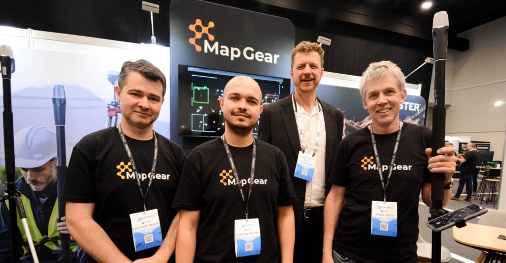
Alistair Hart from Mangoesmapping, a reseller for Map Gear, shares his workflow when working with Emlid Reach RS2 GNSS receivers.
This was filmed during real work for a client, who is rehabilitating a tailings storage facility at an abandoned tin mine in Far North Queensland, Australia.
“Today we’re going to be working with Emlid’s Reach RS2 receivers with both the Base and a Rover and with Reachview 3 to do some setout of an engineering design here on an abandoned mine site in Far North Queensland.”
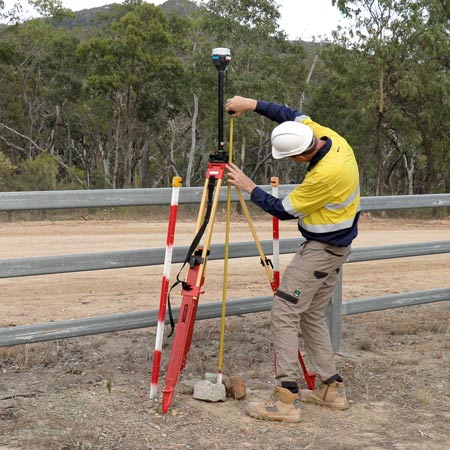
Base Station
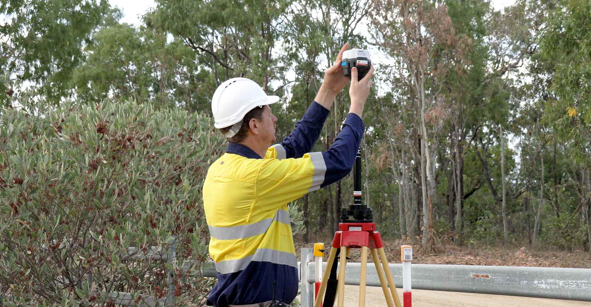
“The first thing we need to do is to set up our Base Station. That’s going to require a tripod, tribrach, tribrach adapter and a small extension pole for the LoRa antenna that comes out the bottom of the Reach RS2.
We’ve established our Base Station and gone into Reachview 3 to adjust the antenna height so that it’s broadcasting an accurate correction for our rover.”
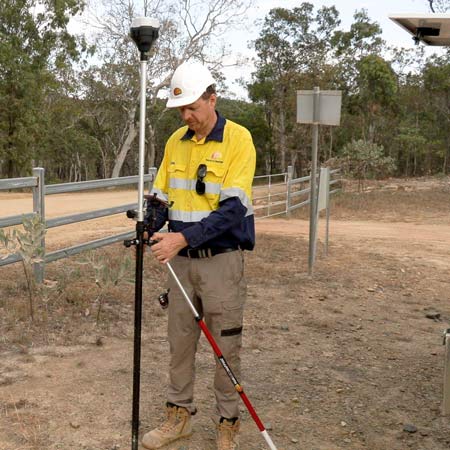
Rover
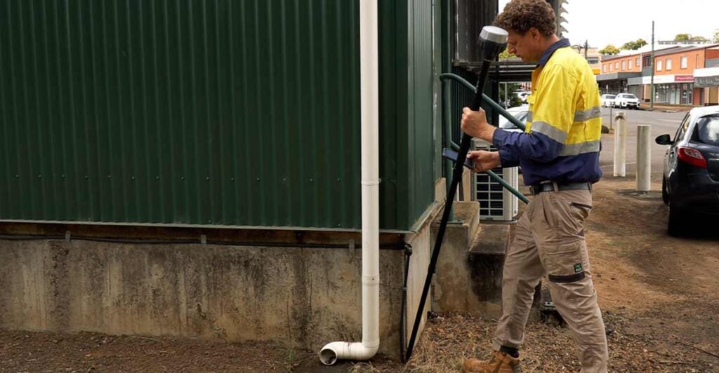
“Now that we’ve got our Base established, we’re going to take our Rover out and connect it to a survey pole. The we will do a couple of quick checks to ensure that we’ve got accurate positioning, and then get on with the job.
I’ve turned the rover on. While it’s booting up I’m just going to put my phone in the quick release device that allows me to have hands-free operation.
You can see that I’ve got a bipod connected to my pole as well. That just frees up my hands to do other things and it makes it a lot easier to work.
If you’re going to chase very precise positioning you want to make sure that the bubble on the top of the pole is absolutely centered inside the bubble level. Having the bipod really allows you to do that very easily.
Next, instead of connecting to the base I’m going to connect to the Rover’s wi-fi network. Once I’m connected to the Rover’s wi-fi I’ll be able to go back into Reachview 3. So I’ve selected the Demo 9 receiver that is our Rover today. Now I can go into my survey jobs.
Double check!
The first thing I’m going to do is double checking of the heights. Each day you just need to make sure that your pole height is correct and reflects the height that you’ve got set up on your pole. So I’ve adjusted my height. Reachview 3 is adding for this particular receiver a 134 millimetre offset to correctly record the antenna height in the software.
We’ve got our antenna height collected, we now have our position. We can now go and occupy some known points and confirm that we’re getting accurate measurements today before we go and begin our field work.
So now that we’ve finished our checks we can pack down our Rover and head out onto site and start getting to work.”
Quick Release Mount
“What I’ve done today is I’ve established a quick release point on the top of my Rover pole. On the front of my vehicle I’ve attached a little quick release point so that I can rapidly mount and dismount my Rover. This allows us to maintain a fix as we drive around the site and quickly mount it back onto our survey pole to keep things moving.”
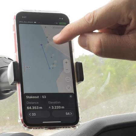
Stakeout locations
“What we’ve got here is the controller connected to the GPS on the bull bar. What that allows us to do is to select a point in the data set and to Stakeout to that particular point. If I wanted to Stakeout number 20 while I’m moving the vehicle I can see how close I am to that point. I can bring the vehicle relatively close before I get out connect the GPS to the survey pole and properly Stakeout that point.”
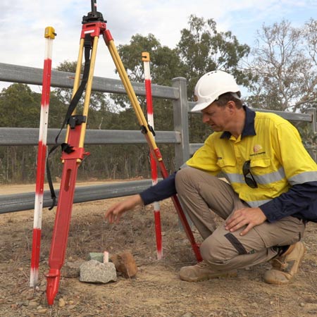
Cut or Fill?
“Right now I’m going to level the pole up and make sure that I’m still within spec. I’m 11 mm off my target and the cut value here is 2.78 meters. Now before I put my stake in I’m actually just going to jump out of this project and go into another project. I can collect a point so that I’ve got a record of exactly where I put the stake and what the elevation was – just good record keeping…
We’ve got a cut value of 2.78 meters here. I’ll just mark my peg up before I even bang it in the ground. It’s easier to write on this way. Not always easy when you’re staking out in such loose terrain like this so it’s always a good idea to keep an eye on how far your survey pole goes into the loose material. You’ll need to compensate for that on your cut values that you’re putting on your posts
Put it in far enough that it’s not going to move and flag it up so the fellows can find it nice and easy.
Today we’re marking out the alignment of a drain. As you can see there’s cut values written on this. That means that the earth moving equipment is going to be reducing the ground level in this area and making this drain wider. The earth movers will take a reference from the base of this peg and use that to understand how far down they have to take the ground around them. There we go – another peg bites are dust!”
Summary
“You’ve seen how we can use Reachview 3 to bring points from an external dataset into your controller. You can then go into the field and identify the location of those points and the relative elevation of the design surface. It’s a very powerful feature that comes with the Reachview 3 application which is free with your Emlid hardware.”
Alistair Hart,
Managing Director, Mangoesmapping